Filtros para Agua TEKLEEN y Accesorios > OBF Series
OBF Series
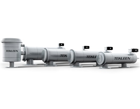
TEKLEEN® brinda ahora filtros automáticos para agua, auto-limpiantes, de la serie OBF, en construcción de acero inoxidable-- al mismo precio que en acero al carbón. Son libres de mantenimiento y le ahorrarán el dinero que de otra forma se gastará en la pesada labor rutinaria de limpieza y reemplazo de cribas, bolsas y cartuchos. Las conexiones de entrada a los filtros van desde 2" a 12", con mallas tan reducidas como 10µ. Los filtros operan con la misma presión de la línea de alimentación (min 40 psi) y la secuencia de autolimpieza se activa por la señal de un sensor de presión diferencial. La presión de operación puede ser de hasta 120 psi. La temperatura de operación hasta 200°F. Acero inoxidable 304L / 316L viene como estándard. La nueva tecnologá para la limpieza de la malla, TEKRINSE®,ahorra hasta el 90% del agua de limpieza.
¡Estamos aquí para ayudar!
Déjenos conocer cuáles son sus necesidades de filtración y nosotros diseñaremos la mejor solución para llevar a cabo el trabajo.
Llene una hoja de datos de la aplicacion para comenzar.
| Cargar archivo | Título del Documento | Tipo de Documento |
|---|---|---|
| Manual de la Serie OBF | Manual | |
| OBF, Diagrama de Cortes | Cutaway | |
| PDF | DWG | Generic OBF Material of Construction | Material of Construction |
| PDF | DWG | OBF2-I Controller Mounting w/ GB5-B | Installation Layout |
| PDF | DWG | OBF2-I w/ GB6, Electric Flush & Electric Pressure Sustaining Valves | Installation Layout |
| PDF | DWG | OBF2-I w/ GB6, Electric Flush & Hydraulic Pressure Sustaining Valves | Installation Layout |
| PDF | DWG | OBF2-I w/ GB6, Electric Flush Valve & Pressure Tank | Installation Layout |
| PDF | DWG | OBF2-P, 3-P, 4-P w/ GB5-B & Hydraulic Flush Valve | Installation Layout |
| PDF | DWG | OBF2-P, 3-P, 4-P w/ GB6-B & Hydraulic Flush Valve | Installation Layout |
| PDF | DWG | OBF2-P, 3-P, 4-P w/ GB6 & Hydraulic Flush Valve | Installation Layout |
| PDF | DWG | OBF2-P, 3-P, 4-P w/ GB6, Electric Flush Valve & Pressure Sustaining Valve | Installation Layout |
| PDF | DWG | OBF4-LP - OBF12-P w/ GB5-B & Hydraulic Flush Valve | Installation Layout |
| PDF | DWG | OBF4-LP - OBF12-P w/ GB6 & Hydraulic Flush Valve | Installation Layout |
| PDF | DWG | OBF4-LP - OBF12-P w/ GB6, Electric Flush Valve, & Solenoid Vent for Piston | Installation Layout |
| PDF | DWG | OBF4-LP - OBF12-P w/ GB6, Hydraulic Flush Valve, & Solenoid Vent for Piston | Installation Layout |
| PDF | DWG | 2x OBF2-P, 3-P, 4-P Filters in Parallel w/ GB7 & Electric Flush Valves | Installation Layout |
| PDF | DWG | 2x OBF4-LP - OBF12-P Filters in Parallel w/ GB7 & Electric Flush Valves | Installation Layout |


